
DFN Happy Hour 39: RC Circuit Introduction
Last Friday (April 16, 2021) we did a soft relaunch, announcing that we’re starting a new set of DFN Happy Hour broadcasts focused around making circuits! One week we’ll make a circuit, the next we’ll make projects around that circuit. The circuits will be low part count, no microcontroller circuits. This 8? 10? 12? Week series (TBD) will be focusing on some aspects of electronics that people who started off learning microcontrollers early in their electronics journey may not have had much experience exploring.
Starting with Capacitors! “Have you tried adding a capacitor?” seems to come right behind “Is your LED backwards?” in terms of troubleshooting tips, but why? What is it doing? And how do we move the capacitor from background support to circuit center stage? To binge out on all things capacitor, check out the videos on Carlyn’s YouTube Playlist on Capacitors and DIY Capacitor project playlist. Keep reading to see more about the circuit coming up this week…
Same DFN Time: Friday at 5:30 pm PST
Same DFN Channel: https://www.twitch.tv/deepfriedneurons
Same DFN Folks (for now…): Barb Noren (BarbMakesThings), Tod Kurt (todbot) and Carlyn Maw (carlynorama)
Last Week Redux: April 16th 2021
Beverages Consumed
- Carlyn: Gin & Tonic w/ Fever-Tree Tonic, Amass Gin (Gastropod Episode on Tonic Water)
- Barb: Newcastle
- Tod: Paperback Brewery (local!) Bunny with a Chainsaw
“Thanks for Existing!” Awards
- Tod: Helicopter of MARS!!
- Barb: Duolingo
- Barb: Crazy animated Japanese website
This Week Preview
This week we’ll look at two LED fade-out circuits that use a capacitor to create the same behavior in two slightly different ways.
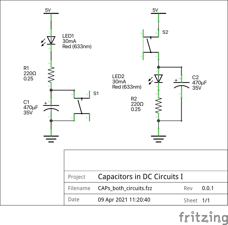
The circuit on the left in Figure 1 is a DC blocker. While the switch is closed, the capacitor is both being discharged and bypassed. The LED shines as expected. When the switch is open the capacitor begins to be charged, the current slowing over time until the capacitor holds it’s maximum charge. The LED will be imperceptibly dim by that point.
In contrast, in the circuit on the right, the capacitor serves as a charge reservoir. While the switch is closed, the current flows through the LED-resistor pair while charging the capacitor in parallel. In this set up, the capacitor charging has little or no impact on the perceptual brightness of the LED. When the switch opens, the charge on on the capacitor will feed the LED until it’s drained.
Amount of time it takes to fade and the rate of change in the brightness involves quite a few factors:
- The human eye
- The material the capacitor is made out of, in this case Aluminum Electrolytic
- The properties of the physical LED
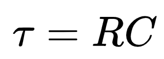
- The the size of the capacitor and the resistor together ( T (tau, seconds) = R (ohms) * C (farads))
In these examples, the resistor has to be a reasonable size relative to the power supply to protect the LED, but also allow sufficient current through that the LED shines bright enough for its application. We will be stuck altering our fade out time by swapping out the capacitors only.
As we discuss how “multiplying” Ohms and Farads and somehow end up with a unit of time (??!!!), a brief reminder of some basic definitions.
- The Ampere (Amp, or A), the unit for current, is a measure of moving charge. It can be referred to as 1 Coulomb / second (Think Watt vs Joule)
- The Volt (V), the unit for electric potential, represents the ability to push a charge past a resistance. Eg. 1V means one coulomb of energy can be pushed past one ohm of resistance per second.
- The Ohm (Ω), the units for resistance, “electrical friction”, is essentially away to talk about how much of a drain on the potential a certain part represents. A 1Ω resistor will consume 1 Coulomb of energy per second, using up 1V of the circuits potential energy.
Building the Circuits
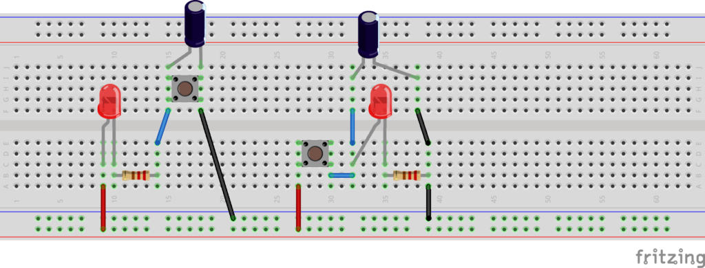
We are using two polarized parts, an LED and electrolytic capacitors. Make sure they go into the circuit facing the correct way.
- The anode is the end of a polarized part that conventional current get applied to, the more V+ side (TMI: oxidation happens here)
- The cathode is where conventional current “leaves” a polarized part, the more GND side. (TMI: reduction happens here)
Parts List
Both circuits use exactly the same parts. Labels based on Figure 1.
- C1 220 uF-1000 uF Aluminum Electrolytic capacitors tested
- R1 220Ω -1kΩ range LED (current limiter for LED as well, so max value is limited)
- LED1 The ubiquitous red led
- S1 A NO (normally open) momentary SPST.
- C2 220 uF-1000 uF Aluminum Electrolytic capacitors tested
- R2 220Ω -1kΩ range LED (current limiter for LED as well, so max value is limited)
- LED2 The ubiquitous red led
- S2 A NO (normally open) momentary SPST.
Pingback: DFN Happy Hour No. 40: RC Circuit Projects : CRASH Space
Pingback: DFN Happy Hour No. 45: Op Amp Oscillator Spaceship! : CRASH Space