
DFN Happy Hour No. 45: Op Amp Oscillator Spaceship!
This week Tod takes the wheel to show off an Op Amp Oscillator on this next round of the DFN Happy Hour. The bloops and beeps will be legendary!
Same DFN Time: Friday at 5:30 pm PST
Same DFN Channel: https://www.twitch.tv/deepfriedneurons
Same DFN Folks: Barb Noren (BarbMakesThings), Tod Kurt (todbot) and Carlyn Maw (carlynorama)
Last Week Redux: May 28, 2021
Post | Video
Beverages Consumed
- Tod: Still luvin’ the Bunny with a Chainsaw from Paperback Brewing
- Carlyn: Dolan Dry Vermouth, Soda, Lime
- Barb: Kona Big Wave Golden Ale
“Thanks for Existing!” Awards
- Barb: Crop-A-Dile punch
- Tod: USB Chargeable 9V
- Carlyn: The humble paper clip
This Week Preview
Last week’s projects used a transistor “astable multivibrator” as an oscillator. One of the problems with this oscillator design is it has two independent RC circuit timing elements. This makes it difficult to set the frequency of the oscillator. But there’s a variation of the astable multivibrator (also called a “relaxation oscillator”) that is much simpler and has only one tuning element. But it does require us to move forward a few decades in circuit design and use an op amp, aka an “operational amplifier“.

The Op Amp
An op amp is an amazing device, especially after you’ve designed with transistors. They have two inputs, labeled “V+” and “V-” and one output “Vout”. Op amps have two power inputs, labeled here “Vs+” and “Vs-“. The two golden rules of op amps are:
- An op amp draws zero current on its inputs (i.e. “infinite impedance”, in reality: 10^12 ohms)
- An op amp attempts to do whatever is necessary to make its inputs match (i.e. make V+ – V- = 0)
The fact that op amps inputs can sense changes on its inputs without drawing current from the circuit it’s hooked up to seems magical, especially if you’re used to BJT transistor circuits. It’s like a circuit spy.
For this week’s circuit, we can reword those rules to our advantage:
- If the difference between the inputs V+ and V- is > 0 volts, Vout = Vs+
- If the difference between the inputs V+ and V- is < 0 volts, Vout = Vs-
Thus, at its heart, an op amp is a comparator. And we’re going to use this comparator as the basis of our oscillator. Op amp comparators are really useful by themselves. For instance, here is a a “6V Detector”, perhaps useful as a “battery low” signal. The “-” input of the op amp is being fed a constant 6V from the voltage divider created by the 10k & 20k resistors (9V * (20/(10+20) = 6V). The op amp’s “+” input is being fed a triangle wave that ranges from 0 to 10V. While that “+” input is less than 6V, the op amp’s output is LOW (or Vs- = -15V in this case). When it goes above 6V, the op amp’s output is HIGH (Vs+ = +15V here).
Op Amp Relaxation Oscillator
Now we have all the parts we need to make an opamp oscillator:
- RC circuit for timing (DFN 39)
- voltage divider to set a particular voltage (DFN 41)
- and now, opamp as a comparator (DFN now!)
Here’s the basic circuit:
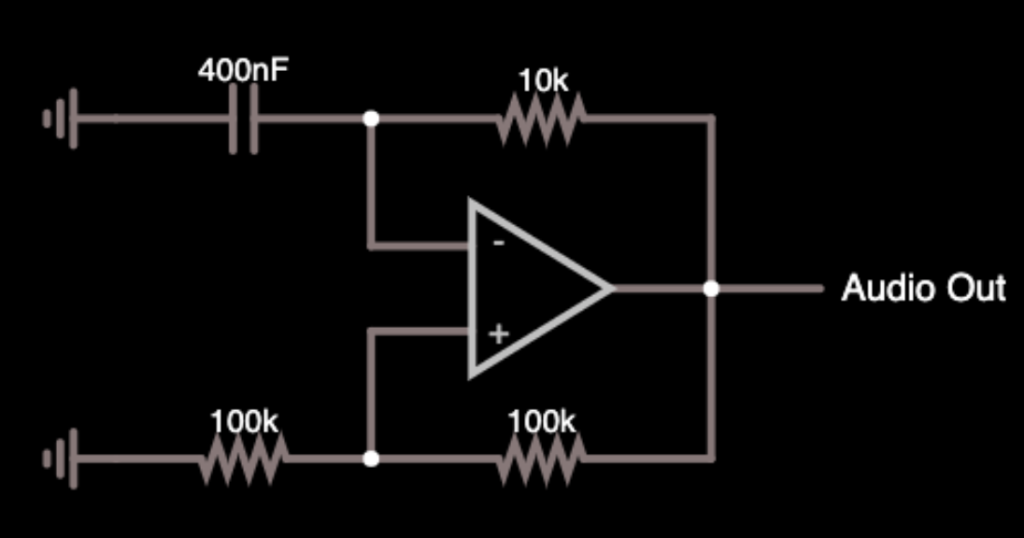
The 400nF capacitor and 10k resistor on top act as the RC timing element. And the two 100k resistors at the bottom act as a voltage divider. The op amp is being supplied +15V & -15V for power. But wait how does this work? The two 100ks act as a voltage divider, taking whatever is at the op amp output (15V or -15V, let’s say 15V to start), divides it by 2 (7.5V), and applies it to the “+” input. At the same time, the 400nF capacitor is being charged up to via the op amp output, through the 10k resistor. All the while the op amp is comparing the “+” and “-” inputs. When the capacitor’s voltage is more than 7.5V, the difference between the inputs goes negative, the op amp’s output slams to -15V. Now the entire process begins again, but with negative voltages. Then it happens again with positive voltages. And now we have an oscillator. Just look at it go!
Simulation of circuit. Try it out yourself!
Op Amp Relaxation Oscillator at 5 Volts
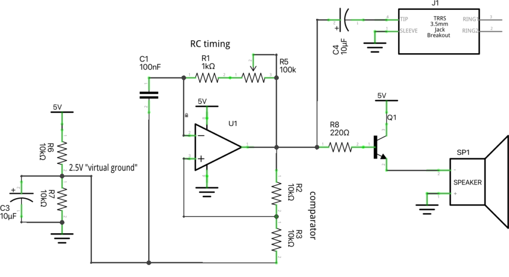
To make the above oscillator work at 5V, we need to do a little trick called a “virtual ground“. The above circuit is assuming the op amp is being driven by a +15V / -15V power supply, where ground = 0 volts. If we’re using a single-supply at 5V, we need to fake a ground at 2.5V using another voltage divider. Adding the “virtual ground” to the above and we get:
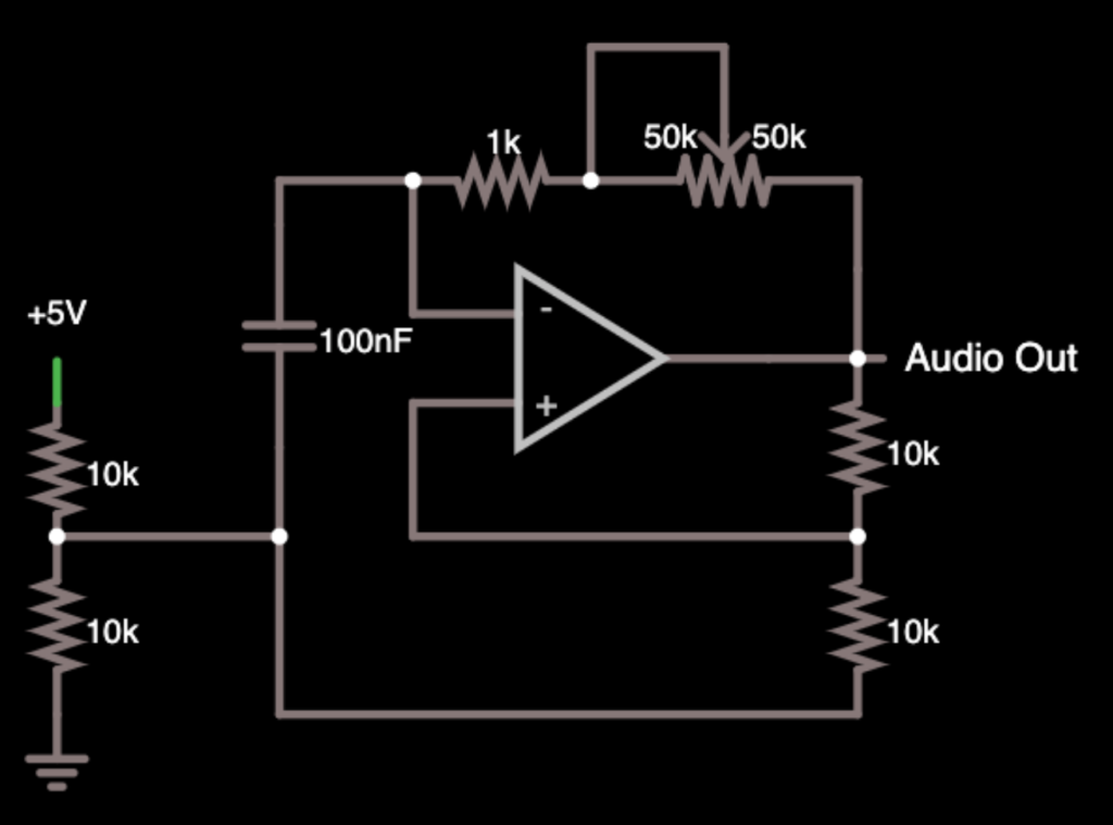
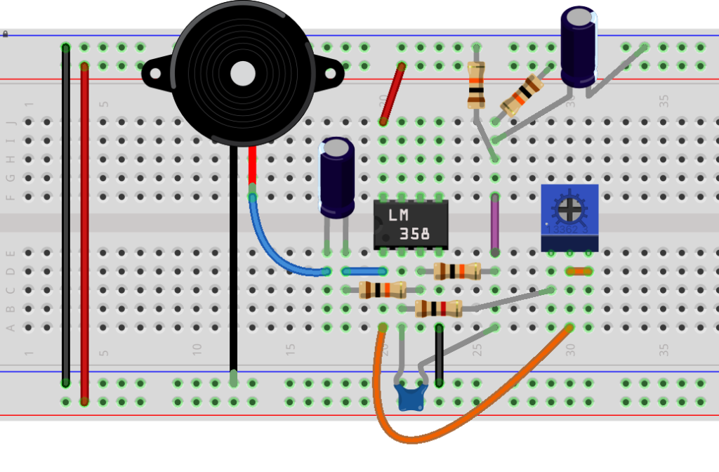
The circuit has been redrawn a bit to make the different sections apparent. And a potentiometer has been added so we can vary the resistance to adjust the frequency. Now let’s redraw that again in Fritzing, adding real components, and notating the different sections:
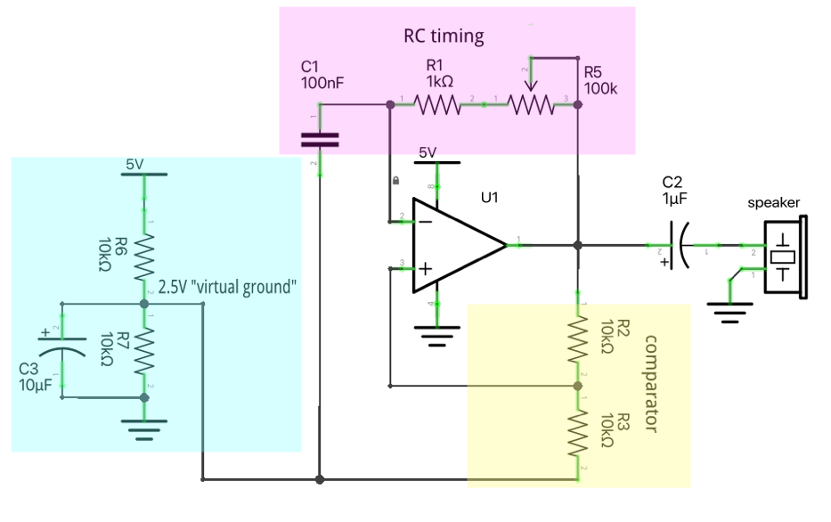
You’ll notice the addition of a capacitor before the speaker. This is to remove the 2.5V offset created by our virtual ground. This is a capacitor in “DC-blocking” mode. Additionally, another capacitor is added to the output of the virtual ground to keep it more stable. This is a capacitor acting as a tiny “charge battery”.
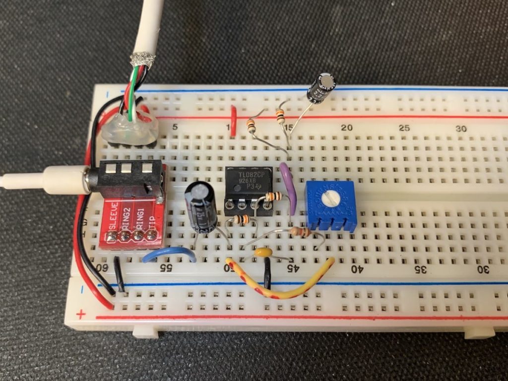
And that’s the whole circuit! Breadboarded up it looks kinda like:
Single Op Amp Version
If you don’t have a dual op amp chip like a LM358 / TL072 / TL082 but instead have a single op amp chip like a LM741, TL071, TL081 or OP27, the schematic and breadboard layout would look like:

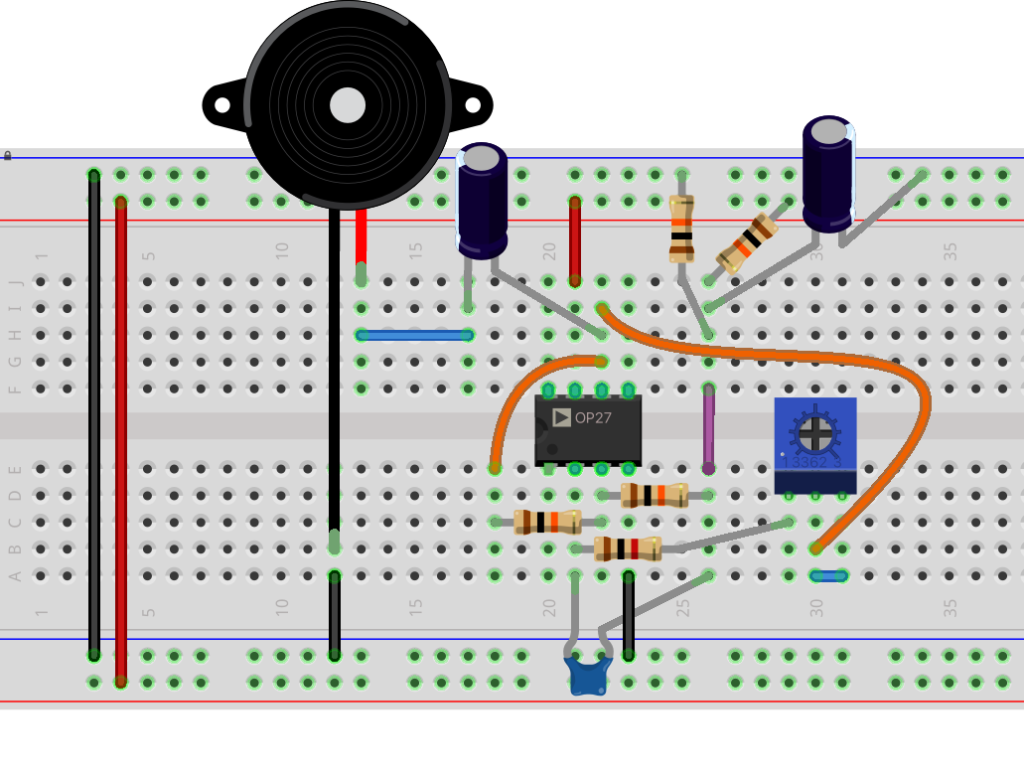
The main difference is that the OUTPUT and Vs+ (aka VCC+) connections are on different pins.
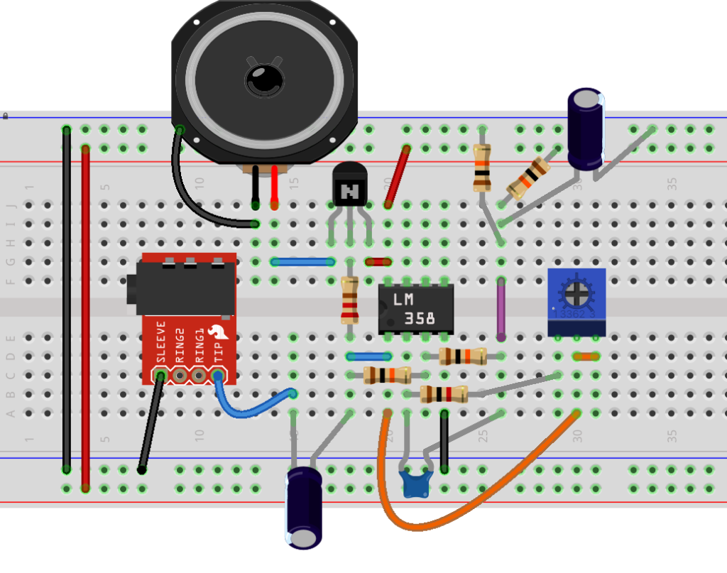
Adding Amplication
You’ll notice that the output loudness is very low. This is because while most op amps are strong, they cannot drive speakers directly. But the output is perfect for the “line in” input of common portable (Bluetooth) speakers. To drive a speaker directly, we need an amplifier. And we can use a trusty transistor for that:
Op Amp Relaxation Oscillator Parts List
This design attempts to use as many of the same value of parts as possible. There is some leeway too. If you don’t have a 100k pot, a 50k or even 10k would work, it just reduces the adjustable frequency range. If you don’t have 1uF capacitors, 2.2uF or even 10uF should work.
The particular op amp isn’t critical. I’ve specified a dual op amp here so we can add a filter later. You could also use a single op amp chip like a 741, TL081, TL071, etc.
For hearing the output, this op amp can drive a small speaker, but you an also hook up a 3.5mm (1/8″) jack and run it to a small portable speaker or even headphones (be careful with volume though)
| Part | Description | option 1 | option 2 |
| U1 | Dual op amp (just about any works TL082, TL072, LM358) Single opamp versions work well too (741, TL081,etc) but breadboard is a little different | Digikey 296-1781-5-ND | Amazon 10-pack |
| R2 | 100k potentiometer (trimmer pot works well) | Digikey CT6EP104-ND | Amazon 10-pack |
| R1 | 1k resistor | from parts | |
| R2,R3,R6,R7 | 10k resistor | from parts | |
| R8 | 220 resistor | from parts | |
| C1 | 100n capacitor (0.1uF) | from parts | |
| C2,C3 | 1uF capacitor (or 10uF, or 22uF) | from parts | |
| Q1 | 2N3904, 2N2222 or similar NPN transistor | from parts | |
| speaker | any small speaker: 8-ohm, 16-ohm, 50-ohm, even piezo should work | AllElec SK-85 | |
| 3.5mm jack | instead of speaker, 3.5mm (1/8″) jack to run to line-in of portable speaker | Amazon 5-pack |
Real-world versions
Here’s one way to wire it up, hewing as closely to the Fritzing diagram as possible. And a video demonstrating what it sounds like.
Further Reading
- Op amp multivibrator at Electronics-tutorials.ws
- Golden Rules of Op amps at Circuitbread.com
- Op amp Cookbook at Nutsandvolts.com
- Golden Rules of Op amps on youtube
Pingback: DFN Happy Hour No. 46: Joyful Noise! : CRASH Space