
DFN Happy Hour No. 41: Nightlight Circuit Introduction
We start round two of our DFN Happy Hour reboot focused around making circuits! We made RC Circuits and RC Circuit Projects first, and now we’re moving on to bipolar junction transistors, photon detection, sensors and biasing. Whew. All that in a 5 component circuit? Goodness.
Read more below to get the BOM and watch some videos to lay some ground work about transistors!
Same DFN Time: Friday at 5:30 pm PST
Same DFN Channel: https://www.twitch.tv/deepfriedneurons
Same DFN Folks (for now…): Barb Noren (BarbMakesThings), Tod Kurt (todbot) and Carlyn Maw (carlynorama)
Last Week Redux: April 27, 2021
Post | Video
Beverages Consumed
- Carlyn: Mint-Grapefruit Juice-Soda-Rum (Dead of Night Distillery, California Silver Rum)
- Barb: 805 Ale
- Tod: Again! Eagle Rock Brewery, “Local Source” Beer, in partnership with Theodore Payne Foundation
“Thanks for Existing!” Awards
- Barb: RJ Hampson, specifically Steampunk Houses Coloring Book
- Carlyn: Practical Electronics For Inventors
- Tod: Handheld LED tester… and James Hoffman for his coffee videos
This Week Preview
This week we’ll look at “dark detecting circuits.” Our main example uses three different types of semiconductors: a BJT (Bipolar Junction Transistor), an LDR (light dependent resistor), and, our favorite, the LED (Light Emitting Diode)!
- LED: Like other PN Junction diodes, an LED is made from two types of doped silicon. P type which uses boron to create “holes” in the silicon lattice and N type which gets overstuffed with phosphorus. To make an LED a PN Junction gets placed in a reflector dish encased in light-scattering epoxy. Boron for P type, Phosphorus for N type.
- BJT: Made of 3 layers of doped silicon, instead of just the two. NPN or PNP, two PN junctions, hence the bipolar.
- LDR: Not silicon but cadmium sulfide. When photons hit cadmium sulfide the normally stable structure gets energized, making it more responsive to an electric field. When light hits them, they become MORE conductive. Their resistance goes DOWN. A note: while ubiquitous in getting started tutorials, LDRs should be avoided in production. Cadmium has well documented negative health and environmental effects. If you have ‘em, use ‘em, sure, but there are alternative circuits at the bottom of this post.
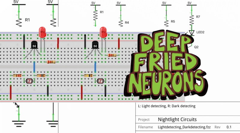
For more information on this circuit and transistors in general, check out this playlist, but for the basic gist of what we’ll be talking about see the figure below.
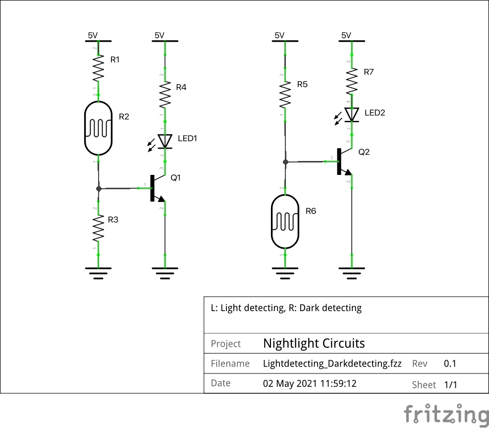
In the circuit on the left, the LDR lives on the voltage positive side of a voltage divider, balanced by a large resistor to ground. As the light gets brighter the resistance of the LDR goes down, increasing the voltage at the base of the transistor, turning the LED on. R1 offers protection to the base of the BJT in case the resistance of the LDR ever drops too low.
In the circuit on the right, the LDR moves to the ground side of the voltage divider, no longer needing a current limiting resistor. When the light shines, again the resistance in the LDR drops, but now that drops the voltage at the base of the transistor to below that of its emitter, turning the LED off in the presence of light.
We’ll talk more about why a voltage divider gets used here, why the LDR can’t just be in series with the base, during the stream. (Hint, it has to do with the forward biasing of that PN junction…)
A night light circuit can also be built with a PNP transistor as well (Circuit simulation of PNP and NPN dark detectors)
Building the Circuits
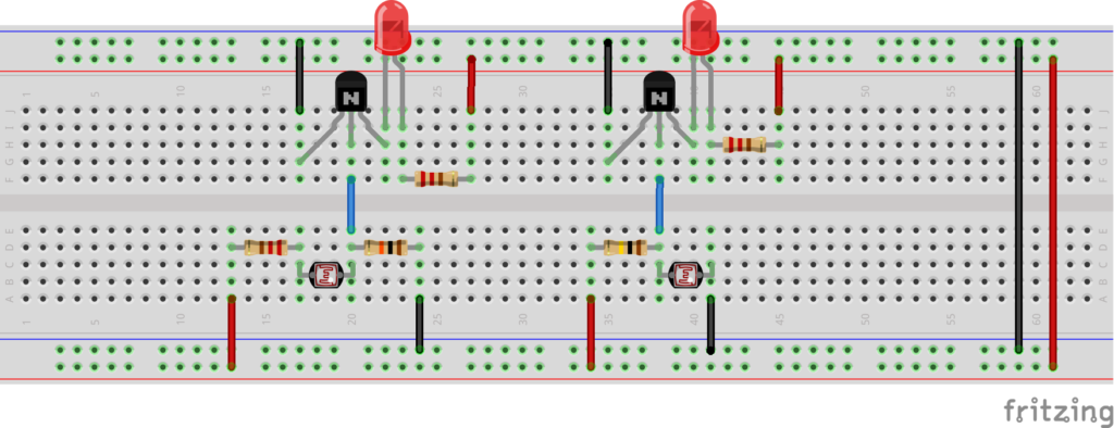
- The TO-92 package is very common for general NPN transistors. Do not rely on having pinouts like in the illustration. Always check the pinout in the datasheet. Common ones that come with standard “getting started” kits include:
- PN2222 Beware: The PN2222 has an EBC pin out when the flat side faces you with pins pointing down (like example), but the P2N2222 has CBE. (PNP version: 2N2907)
- 2N3904 (PNP version: 2N3906)
- BC548 (BC108 Family), (PNP: BC558)
- Unsure about the transistor? Since BJTs use PN junctions like regular diodes, a multimeter with a diode checker can help figure it out.
Parts List
Labels based on Figure 1, which is a circuit with a 5V USB charger supply.
- R1 – Current limiting resistor for base of transistor, between 220Ω-1kΩ
- R2 – LDR, but can be any variable resistor.
- R3 – Balancing resistor for LDR, changing this value will change when the LED goes on and off. This resistor will likely be in the 10kΩ to 1MΩ range depending on the LDR.
- R4 – Current limiting resistor for LED, i.e. between 220Ω-1kΩ
- LED1 – Basic red. The voltage drop of this LED impacts the circuit, so prototype with the kind that will be used in the final project.
- Q1 – NPN BJT transistor like the 2N2222.
- R5 – Balancing resistor for LDR, changing this value will change when the LED goes on and off. Again, this resistor will likely be in the 10kΩ to 1MΩ range. Also provides current limiting protection to Q2.
- R6 – LDR, but can be any variable resistor.
- R7 – Current limiting resistor for LED, i.e. between 220Ω-1kΩ
- LED2 – Basic red. The voltage drop of this LED impacts the circuit, so prototype with the kind that will be used in the final project.
- Q2 – NPN BJT transistor like the 2N2222.
Alternatives
As mentioned, LDRs kinda suck because of their cadmium usage. They also can be slow to respond. Photodiodes and phototransistors offer some alternatives. Links that go into detail about the different light-detecting parts and circuits:
- https://www.electronics-tutorials.ws/io/io_4.html
- https://www.electronicshub.org/light-sensors/
- https://www.buildcircuit.com/dark-sensor-using-transistor-phototransistor-and-photodiode/
Example circuits:
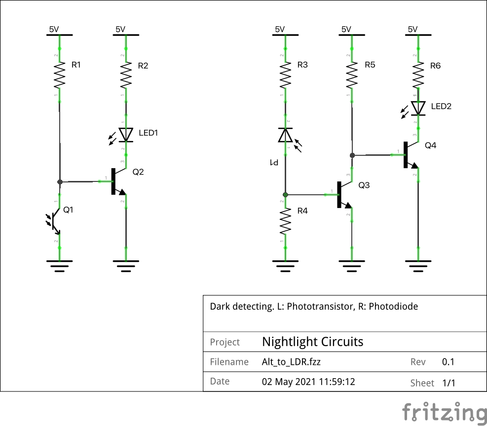
The circuit on the left swaps a phototransistor in for the LDR. It will behave a little differently since phototransistors have a faster response time. The resistor values will need to be changed up depending on the part.
The circuit on the right uses a photodiode. This circuit has more of a if (!isLight) { led = on } than if (isDark) { led = on } action than the others. Since photodiodes pass much less current than LDRs and many phototransistors, a circuit using one will likely need extra signal amplification. A pair of transistors can do this. In the configuration shown, using two NPN transistors, that first transistor in the pair connects the base of the second to ground, essentially creating a “not gate.” This inverter means the photodiode moves back up to the voltage positive side of the voltage divider. Using a PNP as the second transistor would prevent the inversion (à la Sziklai Pair (seek-laa-ee)).
- The photodiodes block current when they don’t receive light. The symbol reflects that, being “reversed bias”
- Simulation of 3 different transistor pair amplifiers in inverted logic circuits
Parts List
- R1 – Current limiting for Q2 transistor base and Q1 balancer, depending on Q1’s characteristics. Can be quite high. *
- R2 – Current limiting resistor for LED, i.e. between 220Ω-1kΩ, depending on LED and power source
- LED 1 – Indicator LED, The voltage drop of this LED impacts the circuit, so prototype with the kind that will be used in the final project.
- Q1 – Phototransistor. These vary by wavelengths detected, whether they have a third leg to provide additional base current, Darlington types are amplified and may work better in this context. This circuit is really just a starting point.
- Q2 – A General purpose NPN BJT transistor like the 2N2222 should be a fine place to start, but there may be one that works best with the phototransistor you have.
- R3* – Current limiting resistor for P1 and Q3, i.e. between 220Ω-1kΩ, depending on LED and power source
- P1 – Photodiode. Try an LED wired in backwards for giggles.
- R4* – Among other things, ensures that Q3 VB stays high enough relative to Q3 VE
- R5* – Current limiting for Q3
- Q3 – General purpose NPN BJT transistor like the 2N2222. Round one of amplification, also a “not” switch because the emitter is tied to ground.
- R6 – Current limiting resistor for LED, i.e. between 220Ω-1kΩ, depending on LED and power source
- LED2 – Indicator LED, The voltage drop of this LED impacts the circuit, so prototype with the kind that will be used in the final project.
- Q4 – General purpose NPN BJT transistor like the 2N2222.
* These branches of the circuit can, and to save power should, be pretty high impedance. The resistor values can be as high as you can get away with. Notice in the circuit simulations they have very high values (1M, 30k, etc.).
Pingback: DFN Happy Hour No. 42: Light in the Dark Projects : CRASH Space
Pingback: DFN Happy Hour No. 45: Op Amp Oscillator Spaceship! : CRASH Space