
DFN Happy Hour No. 43: Good Vibrations
This week the combination of our transistor circuit and the RC circuit gets us dancin’! At least oscillating anyway. Bring on the multivibrator circuits in Round 3 of the DFN Happy Hour with circuits.
Same DFN Time: Friday at 5:30 pm PST
Same DFN Channel: https://www.twitch.tv/deepfriedneurons
Same DFN Folks (for now…): Barb Noren (BarbMakesThings), Tod Kurt (todbot) and Carlyn Maw (carlynorama)
Last Week Redux: May 14, 2021
Post | Video
Beverages Consumed
- Tod: Golden Road Mango Cart
- Carlyn: Grapefruit, Lime, Gin and Soda
- Barb: Kona Big Wave Golden Ale
“Thanks for Existing!” Awards
- Barb: Wingnuts and other bits and bobs of hardware
- Carlyn: Meredith Bull and her amazing cat-sample based music
- Tod: Ikea globe lamp
This Week Preview
Astable Multivibrator circuits combine what we’ve learned about RC circuits and transistors. These days a search for “multivibrator circuit” will wind up on a page with a 555 timer. The 555 timer has a flip-flop (bistable multivibrator) and some comparators, and generally represents the normal way to inject some oscillation into a circuit. I’ve heard it described as the teddy bear of IC’s, so loved and ubiquitous it is. The Evil Mad Scientist 555 wiki page, and their Three Fives kits (through-hole and surface mount) have fabulous information on the 555.
We are not going to be using the 555 this week. We’re going to build a flip flop (bistable multivibrator) and a free running relaxation oscillator (astable multivibrator) by hand with just transistors, resistors and capacitors.
The Flip Flop
A single flip-flop circuit isn’t super useful on its own to project builders building interactions on human scale. It’s just a device that remembers its position, which a toggle switch or a bank of DIP switches can handle nicely. But let’s say a project needs to remember hundreds, thousands or millions of switch settings. Or loop through different setups at millisecond speeds. And do this while being smaller than a sky scraper. Tiny little flip-flops make all that computer memory and logic possible. They matter to us this week because understanding the bistable multivibrators will help make the astable multivibrator, our real goal, more intelligible. Let’s build up from a circuit we already know, a switch “not” on the base of the transistor similar to our dark detector logic.
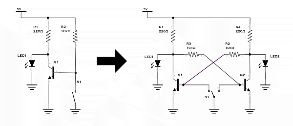
- Step 1: Transistor being turned off with a switch
- Step 2: Two transistors, one SPDT
- Step 3: Connect Control side of Q1 -> Load side of Q2, Control side Q2 -> Load side of Q1, and we have the the bistable multivibrator (with 2 SPSTs instead of the SPDT shows off the change)
Getting Astable
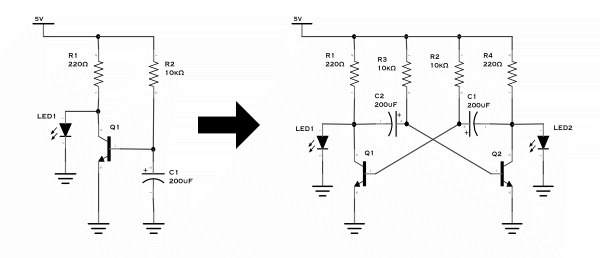
Humans epically suck at tapping buttons repeatedly at a perfect intervals for hours on end, so we want to be able to use an RC circuit to do the work. An astable multivibrator or a “relaxation oscillator” gets built up in a very similar way to the bistable, but replacing our switch with a capacitor.
- Step 1: Transistor being turned off by a capacitor filling
- Step 2: Double it again
- Step 3: Swing the Caps
- Step 4: Clean it up
- Examples: Driving Bigger loads NPN PNP
- More examples: Nuts and Volts Transistor Cookbook Part 6
- Can you combine more than two? YES! tutorial, simulator
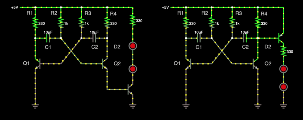
Driving more than a wee little LED might happen for our projects this week, so I wanted to show what that would look like using another NPN transistor (left), and a PNP transistor (right).
Breadboarding the Astable Multivibrator
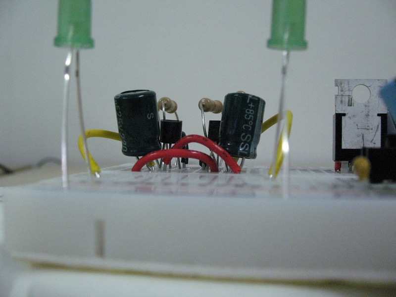
This DFN episode takes me way back into CRASH Space history. I built a discrete part multivibrator circuit at CRASH Space in March 2010 while preparing for a class at the deeply missed Machine Project. That wall and those bench-tops look squeaky clean because they’re new! I still love this breadboard layout for an astable multivibrator circuit because it looks like a little crab.
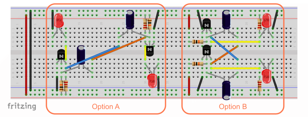
This layout would be very hard to model in Fritzing with the parts so smashed together so I made a couple of other options to try.
Parts List
- 2 general purpose NPN Transistors like PN2222 or 2N3904
- 2 current limiting resistors, 220-1k Ω
- in the schematic example: 220Ω
- in the pictures on flicker: 330Ω
- 2 RC pairs:
- in the schematic example: 10kΩ and 200uF
- in the pictures on flicker: 10kΩ and 220uF
- 2 LEDs
These circuits will blink a few times a second, but the RC pairs don’t have to be the same. Try this astable multivibrator calculator to figure out what values to use for your own. It requires a lot of inputs, but provides reasonable defaults.
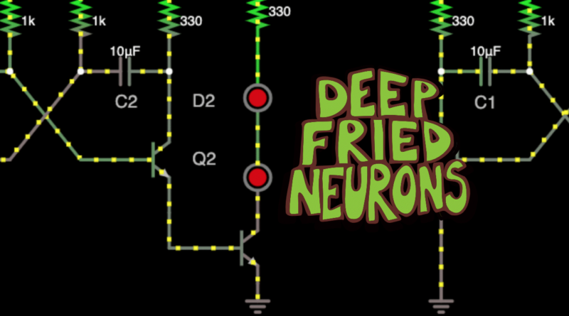
One shot pulse generator
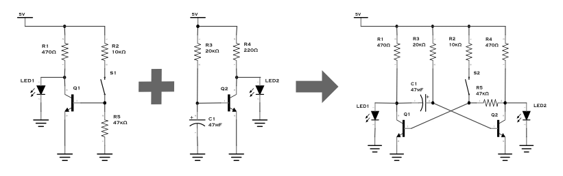
The bonus circuit on offer this week is the monostable multivibrator which combines one side of bistable with one side of astable. There are several schematics for this circuit depending on the specific application. A very simple one, using a manual trigger but keeping the collector-coupled pair, is shown above.
- Super simple monostable circuit (model of circuit in figure above, drawn two different ways, with protection diode)
- Same as above, with pull down. as seen in the Nuts and Volts guide mentioned previously (based on figure 10)
- Using a switch on a third transistor to short Q1 as seen in this model provided by Falstad
- Example with AC input signal, based on illustration in Practical Electronics (Figure 4.68, pg. 448), also shown on the Electronics Tutorials page.
- Single transistor one shot
Pingback: DFN Happy Hour No. 44: Astable Projects : CRASH Space