
Take Apart Tuesday No. 8: Saw III Digital Voice Recorder & LOST Homage
 Yay! Another Take-Apart-Tuesday write up! I’ve been distracted by CRASH Space meta, but here’s one of the several dismantlings we’ve done since the last time I posted.
I’ve written about how nice it is to be able to buy electronics supplies locally a few times. All Electronics is one of those LA vendors. Tom brought in one of the SAW III digital voice recorders they sell for around 2 bucks in January, but, lets face it, it creeped me out. So what better to do than to Take it Apart!
Toys and random schwag are great resources for hacking projects. Frequently you can get whole working circuits for cheaper than an IC alone. I tried to source comparable boards / chips and the next cheapest thing I found in a board was $6.95 (What looks like the Aplus APR9301 at Electronics123). I found a chip alone at Digikey for $3.84 (The Nuvoton ISD1700 ChipCorder® Series)
As Make Magazine pointed out back in 2008, GetLoFi has a write up showing what resistor to replace with a potentiometer for pitch control (R4) how to add a phono jack, etc. Briefly mentioned is hooking one of these up to an Arduino board via transistors, so that’s what I’m going to show in this article.
A word (or two) on transistors
Ahh transistors. Transistors are the electrical components making the information age possible. For example, they are what Moore’s Law is all about. Computer chip manufacturers keep figuring out ways to double the number of transistors fitting on the same surface area every 18/20 months. This means exponential leaps in memory, sensor accuracy, processor speed, etc. In other words, it is how we get so much fun obsolete-6-months-after-purchase stuff to take apart.
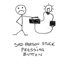
What can transistors do that make them vital to the cause? Well, in the beginning, there was the button. And the button had to be pushed by a person in order to make anything happen. And that was bad because we’re a slow and distractable sort of species with more fun stuff to do than pushing buttons and flipping switches. Do you watch LOST? Do you know how they spent season two pressing a button every 108 minutes? Well, if they had had an Arduino board and a transistor they could have written a quick little program and the darn hatch never would have blown up and maybe we could have had at least another season and I wouldn’t be so sad this week… But I digress.
So the magic of a transistor is that you can have one circuit “press a button” in a separate circuit which may have different voltages, current flows and other properties with no human actively involved.
 |
 |
Transistors are made by combining semiconducting materials. Semiconductors come in two flavors. The N type and the P type. N type semiconductors tend to have extra electrons that they are happy to give away. They get the extra electrons because the silicon used to make them has been “doped” with phosphorous or arsenic.
In P type semiconductors boron or gallium are added to the silicon. Those additives cause cozy little holes in the silicon lattice. These holes make great homes for the overcrowded electrons in N type semiconductors.
When you put a layer of N-type next to a layer of P-type and apply current in the correct direction, the electrons will move from the N Type to the P type. Many diodes are made this way. Think of them as taking advantage of a kind of electrical capillary action. When you slap on an extra N-type layer you get an NPN transistor. One N-layer is connected to a pin called an Emitter. Another N-layer is connected to a pin called a Collector. The P-layer is connected to the pin commonly known as the Base.
When you apply a current via a positive voltage to the P-type layer through the Base of an NPN transistor you’re basically flooding the porous P-type material so it is electrically-wet enough to allow electrons to pass from the Emitter N-layer to the Collector N-layer. If it sound weird for electrons to go in the Emitter and out the Collector, remember the direction of electrons is the opposite of how we talk about current.
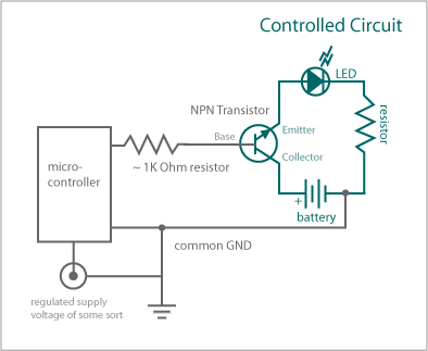
Here is an example schematic of how you might wire something up. The gray circuit controls the teal circuit.
What does all this actually look like in a pretending-to-be-practical application?
Back to Our Saw Doll
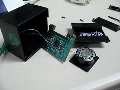
Step 1: Take It Apart
The circuit board for the the digital recorder has a few things coming off of it:
– a Microphone
– a speaker
– Leads to the power supply
A heads up: all of the leads are very fragile. I had to replace/re-solder a few several times while I was mucking about with it.
Additionally there are two buttons: S1 for record and S2 for playback
Step 2: Prep for Use with Arduino
So there are a few things that need to be done if you want to pirate a battery powered device with switches for use with a microcontroller.
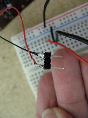
- Step 2a: Desolder the buttons and replace with wire leads (shown below already attached to breadboard)
- Step 2b: Remove the power supply and either replace the existing leads with 22 AWG wire or solder the existing wires to headers.
If you wanted to you could also replace R4 with a potentiometer like in the GetLoFi example, but I didn’t do that.
Step 3: Wire it up
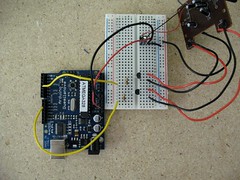
Here is an illustration of the basic wiring.
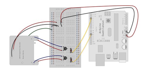
The big things to notice:
– Power to the breadboard is from the Arduino 3.3 V supply
– When having one circuit communicate with another circuit, the most important thing is that they agree on where ground is. There are two wires going to the SAW III board from the breadboard to make that common ground connection. The first is part of the power supply hook up. The second is an extra wire that is wired into the ground plane at a separate position. I made it dark green in the picture. This wire could be used to create the common ground while using the original battery supply to drive the digital recording circuit if you want to go that route instead.
– There is a 1k current limiting resistor connecting the signal lines from the Arduino to the base of the PN2222 transistors.
Step 4: Code it Up
Here is the most basic code that records a sample, then plays it, records, then plays, records than plays, etc. It is suuuuuuuper annoying. Just so you know. And here is the video to prove it!
Homage to LOST project
Because I’m going to miss LOST so much, I went ahead and wrote a little program that will play a recorded clip every 108 minutes. Thrown in is record-on-button-release functionality to reset the message meant for use with a the same wiring as above with a momentary switch added to pin 2. I suggest “DON’T DO IT JACK”
If people have their own projects that they’ve done with these things, I’d love to see them.
Thanks for this, Carlyn! exactly the stuff I need to see about how basic electronics are used and controlled. I’m going to learn a LOT from you, me thinks!
Pingback: Crash Space » Blog Archive » Found @ CRASH Space No 5. – Tactile Swiches