
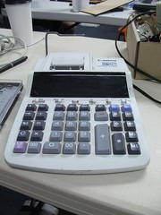
Take Apart Tuesday No. 7: Keypad from Canon MP27D
Running way behind, but I think y’all will forgive me. We’ve been doing some great Put-Together-Tuesdays since the last time I posted with a SpeedMake on March 2nd and BrushBot assembling on the 9th. If you’ll look waaaay back with me to February 23rd, though, I’ll tell you about the Canon MP27D.
 |
 |
While there is some fabulous motor fun in this machine, there is also a keypad that uses something called row column scanning to do it’s business. I bring this up because it is pretty common to want more buttons in your project than your micro-controller has pins. Also, the board they’re using is one of the easiest circuit boards to completely reverse engineer that I’ve seen in awhile because it has no parts on it. So for keypad circuit stealing, keep reading.
How did I know it was Row Column Scanning?
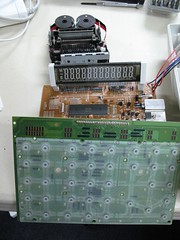
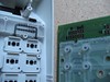
There are 3 general sections to the circuitry in this machine. The first chunk is the main circuit board with the logic chip and display on it. The second unit is the printer. The third is the keypad.
The adding machine keypad holds 37 momentary buttons. Additionally there are 6 switches that have a total of 20 possible positions between them. This means there are 57 input readings the micro-controller needs to collect at any given moment . The gray cable wire between the keypad board and the main logic board only has 30 wires, almost half of what you’d need to transmit the key/switch information directly. There are no mysterious black-box ICs anywhere on the keypad board to do any compression, so something else has to be happening. The most likely candidate: Row Column Scanning
What is Row Column Scanning?
Row Column Scanning basically takes any group of information and gives each item in the group a unique identifier by combining a row coordinate with a column coordinate. For those of you who remember, this is exactly how you play the game Battleships.
To review: lets say you have 16 items and want to represent them row-column style using a 4×4 matrix
     1     2     3     4
A    A1    A2    A3    A4
B    B1    B2    B3    B4
C    C1    C2    C3    C4
D    D1    D2    D3    D4
In other words 1 = A1, 2 = A2, etc.
1 2 3 4 5 6 7 8 9 … 16
A1 A2 A3 A4 B1 B2 B3 B4 C1 … D4
This can seem pretty overwrought, but it means getting 16 digital inputs (or outputs) while only using up 8 pins on your micro-controller.
How’s that you say?
Instead of thinking “rows” think output pins. Instead of thinking “columns” think input pins. In other words, each row is attached to a different pin on the micro controller and each column has it’s own pin, too.
So if you wanted to see if button B3 was being pressed you’d light up row B and listen on the pin attached to column 3. If you get a reading, the switch at that intersection is closed.
     1     2     3     4
A    A1    A2    A3    A4
B    B1    B2    B3    B4
C    C1    C2    C3    C4
D    D1    D2    D3    D4
The process is called Row-Column-Scanning because it’s more typical to scan through all the inputs at once rather than to check each button individually. Programmaticly this requires one to:
- set the pin attached to Row A high,
- then sweep through a check all the columns
- set Row A back to low
- set Row B high
- and then check all the columns again, etc.
Identifying Rows and Columns in Real Hardware
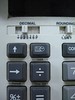
To steal this key pad, I needed to identify the rows and columns electrically. The physical buttons are in a nice little grid pattern, but the underlying circuit doesn’t have to follow the same layout.
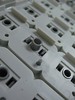
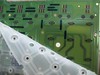
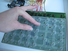
The mechanical engineering for the buttons on the adding machine follows a typical formula for keypads by using 3 three layers: a hard outer shell, a flexible layer with conductive material selectively applied and a circuit board with contacts exposed. Pressing the button deforms the flexible layer, mushing the conductive material into the contacts on the board, thereby closing the circuit.
 |
 |
 |
 |
 |
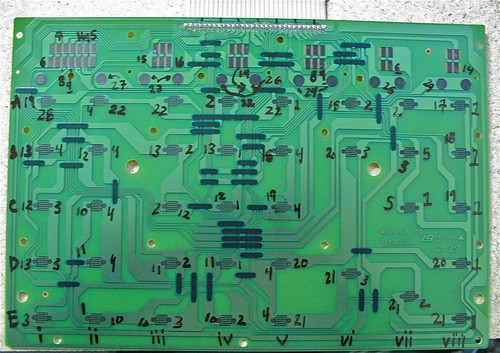
To properly map out the board I needed to test continuity between each exposed contact and the pins across the top. What I did was place one probe of my multimeter on a contact and then run the other across the top.
This is the board numbered out:
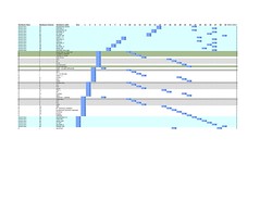
Once I had that done all that I put my pin info in a spread sheet that looked like this:
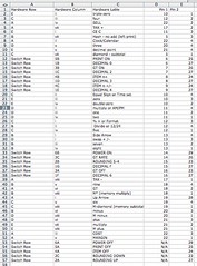
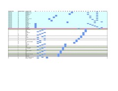
And then it looked like this:
 |
 |
 |
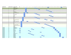 |
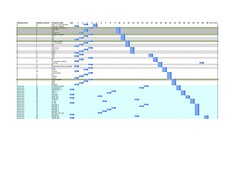
And then I fiddled around with it until it looked like this:
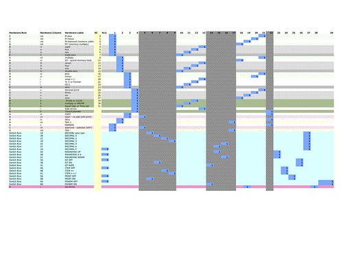
Doing this helped me see relationships between the pins and make decisions as to what the most effective way to code a scan would be.
To do the wiring I desoldered the ribbon cable and soldered in 22 AWG solid-core wire which is easier to use with a breadboard. I didn’t solder up all the leads, just the ones I thought I might use in the code. I used yellow for “Rows” and red for “Columns”
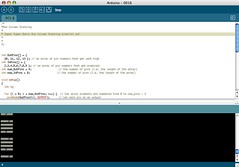
I wrote up two Arduino code examples. One that prints out a “picture” of the rows and columns via a serial connection, Sending a 0 when there is no button press found and 1 when there is a press detected.
 |
 |
The other is a quick example of how you might integrate Row Column Scanning with a switch / case statement. The CS column in the last table I included are what the case statement numbers would be for each button if I had finished writing it out.
They both use nested for loops where the outer loop is the one that sets the Row/Output pins high and the inner loop sweeps the columns.
Just a reminder, to use this code you’ll have to put up with yet another layer of abstraction. Each button now has yet another set of coordinates – which ARDUINO pins they map to. Circuit boards pins 1, 2, 3, 4 are Arduino pins 10, 11, 12, 13 for example. Pins 10, 11, 12, 13, 18, 19, 20 and 21 on the keypad board are attached to pins 9, 8, 7, 6, 5, 4, 3 ,2 respectively.
Good luck!
Incredible writeup Carlyn! Now I know how all the calculators I’ve taken apart actually work. I’ve heard of row-column scanning before, but now I really understand it. What’s more, I know how to figure it out for next time. Thanks!
I NEED A KEYPAD TOUCHKEY FOR A MP27D FOR THE MINUS KEY
Pingback: carlynorama | Intel Experience Store – Day 17 Recap: Some days are tidying days.