
Take Apart Tuesday No. 4: Apple StyleWriter 1200
This week we ripped apart an Apple StyleWriter 1200 and got one of its stepper motors working! See, we don’t just kill things.
Once again How Stuff Works comes to the rescue with a great article on inkjet printers. Give it a quick glance, especially the Inside an InkJet Printer, before you look at the dismantle porn on flickr so you can get a sense of what you’re looking at.
This poor printer had clearly been languishing in a garage somewhere, with bugs and dirt and stray pennies… we’re happy it’s now in a better place.
Here’s the flickr set: http://www.flickr.com/photos/carlynorama/sets/72157623309152076/
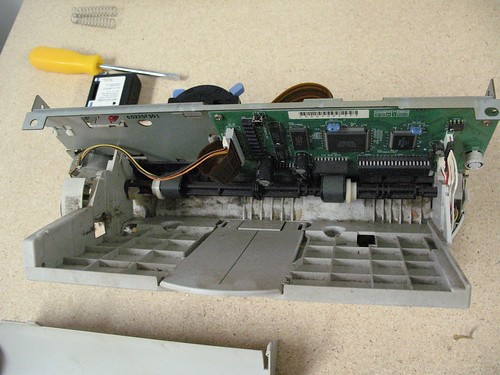
Last week we had a motor in our circuit inducing current for an LED so now we have the perfect segue for looking at a motor, well, being a motor. We captured two stepper motors from the StyleWriter 1200 and got a 4 phase 5 wire unipolar stepping motor to do its thing.
Salvaging a Stepper Motor
A basic summary
There are many very good write ups on stepper motors online.
- The frequently sited Control of Stepping Motors by Douglas W. Jones THE UNIVERSITY OF IOWA Department of Computer Science
- Stepper Motors by Ian Harries
- Tom Igoe‘s Stepper Motor Control
- And if you want some take-apart-extreme, Duck Tape Engineering has posted pictures of the inside of a stepper.
Stepper motors are the go-to motors when precise movement is more important than weight, torque or energy efficiency. Their axles move in discrete steps, hence the name. So, for example, the motor I’m writing up here can be moved in 7.5° increments, dividing a full 360° turn into 48 discrete steps.
Unlike a DC motor that just spins freely in one or two directions, stepper motors need precise commands to each lead wire to get any kind of interesting behavior. The motor will just sit there, shudder and try to elicit sympathy if you get it wrong. It is not a pretty sight. Which is why microcontrollers, like the Arduino, are used to control them.
Motors generally have different power requirements than microcontrollers, and since they use changing currents and magnetism to generate motion they make for very electrically noisy additions to the circuit neighborhood. As a result keeping the motor’s power and the microcontroller’s power separate becomes necessary. You can accomplish that separation with transistors. However, transistors are bulky so various electronics companies have made integrated circuits that cram a whole bunch of transistors into one cute tiny little package. Well maybe not that cute, perhaps more black and svelte.


| Part no. 1147194 | |
|---|---|
| Manufacturer | TEXAS INSTRUMENTS |
| Manufacturer no. | ULN2003ANE4 |
You can generally nab anything called an H-Bridge, Darlington Transistor Array, Quadruple Half-H Drivers, etc. The L293, SN75441, ULN2003 are all chips you might notice in examples and they all do the trick. Important caveat: they do not have identical wiring diagrams, i.e. they get integrated into circuits differently because how each pin on the IC behaves is different from chip to chip. It is best to use the same chip as the example you are copying unless you are comfortable reading a datasheet.
For us that night, I knew where there was a link to pictures of a L293 online and I had a L293 in my kit. So that is where we started.
What Happened That Night
So while I was starting to wire up the board, Justin jumped in to find out what kind of stepper we were dealing with. My old stepper example used a 4 wire bipolar stepper and this one had 5 wires sticking off it.
The motor’s label told us it was a Mitsumi M42SP-7. According to the datasheet it is a 4-phase unipolar stepper motor. Mitsumi motors are fairly common and here is a link to their full motor products list. The other motor in the printer was the M42SP-4N.
Justin discovered the example on the Arduino site using a 5 wired stepper and we decided to follow that.
Since wire colors on salvaged motors are fairly arbitrary we had to figure out what each wire was connected to. Ian Harris’ site has the clearest explanation on how to do that.
Find the common wire
In a 5 wire 4 Phase Unipolar Stepper Motor four of the wires are attached to coils in the motor and the fifth is a common source of power.
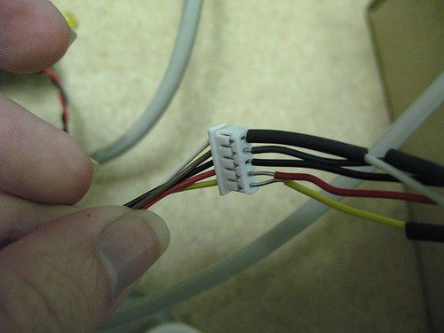
The first thing we had to do after extracting the motor was attach lead wires to it so we could use it with a breadboard. The white connector at the end of the motor’s soldered on lead wires is not the same spacing as the spacing on a breadboard so we couldn’t just use the 0.100″ breakaway male headers that fit into breadboards. The 22 gauge wire I had on hand also seemed to be a bit thick, but we managed to squish its ends a bit with pliers and get the wire into the motor’s interconnect.
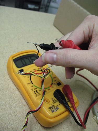
Once those wires were attached, Justin tested resistance between all the leads on the wire. Most of the wires had a reading around 150 Ohms between them, but the black wire in the center read 75 ohms to each of the other wires.
My recreation:
As Ian Hayes Says:
The Common Power wire will be the one with only half as much resistance between it and all the others. This is because the Common Power wire only has one coil between it and each other wire, whereas each of the other wires have two coils between them. Hence half the resistance.
We had some debate about whether that wire was really supposed to go to power or ground since it was black, but to power it goes.
Hitching up the Arduino
With the board finally wired up (a bit sloppily I will admit), Thereon lent his Arduino to the cause and we connected it up to the motor as indicated in the example on the Arduino site. We did the best we could given that we were using a different chip and a different motor. Basically, I guessed. After loading in David Cuartielles’ easy code we got stuttering but no real movement from the motor. (if you have no Arduino experience you can start here). No biggie. Swapping which wires were two and three got us motion! Yay! (I’ll explain why this worked later)
And the next day…
So the next day I come in and not so much with the working motor. Not that unusual with a Physical Computing project, so I took it as a chance to really figure out which wire was which following Ian Hayes directions which I mentioned before. He shows a clear way to figure out the order of your coils on a 4-phase unipolar stepper. After running the common power into a supply voltage you pick any of the remaining wires and connect it to ground. He calls it “wire 4” arbitrarily. By tying each successive wire to ground and seeing how the motor behaves you can ferret out which wire is tied to which coil.
The results:
- Wire 1 – Yellow
- Wire 2- White
- Wire 3 – Red
- Wire 4- Brown on motor / Green on lead wire
There were other tips on how to figure this out on a pic chip (type of microcontroller) reference site, but it was better for motors with a different number of leads than our 5 wire unipolar motor.
Hayes goes on to explain how to find the right sequences for a 5 wire / 4 phase unipolar motor. Cuartielles’ code matches up with Hayes recommendation with the following wiring (via the L293 in the middle)
- Arduino pin 8 -> wire 1 / A / Yellow
- Arduino pin 9 -> wire 2 / B / White
- Arduino pin 10 -> wire 3 / A’ / Red
- Arduino pin 11 -> wire 4 / B’ / Brown-Green
Notice I added the A/B/A’/B’ to this list. Many discussions of stepper motors talk about wires in terms of pairs: A/A’ or 1a/1b, etc. In our motor what are being called wires 1 and 3 are a pair and wires 2 and 4 are a pair. The reason swapping the wires the night before worked is because what I had done was to wire two wires relating to the same pair in succession when really the key to stepper motor control is making sure that all the different coils are properly interleaved. So, for example, Jones’ representation of what what your microcontroller pins need to do to create motion (version below) looks way fancier than the simple step through that Curtielles is doing in his Arduino code even though they are doing the same thing. Again, this is because Jones is grouping his wires by pair rather than by the coil sequence.
  Winding 1a 1000100010001... (our yellow wire)
  Winding 1b 0010001000100... (our red wire)
  Winding 2a 0100010001000... (our white wire)
  Winding 2b 0001000100010... (our brown/green wire)
              time --->
Not the problem.
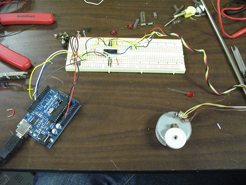
So now confident in the fact that the wires were all lined up correctly, I was still facing a stuttering motor. My next guess was the power supply. Because in the Arduino example we were copying they had gotten away with using 5 V from the USB port I had cheated and done the same thing by tying the motor power supply pin of L293 into Arduino board’s 5V pin-out. The M24SP-7 is a 12V-24V motor, and while, for what ever reason, it had decided to humor us the night before it was no longer in any mood to make do with a paltry 5 volts. I now suspect that this was because my computer that night was plugged in and the next day I was running off a battery. It’s an untested theory. Adding a 12v external supply into the mix solved the problem. (See the note in this picture for where that 12 V supply went into the breadboard)
More fun with code
So back to the video at the top of the post.
I have a longer history with Tom Igoe’s bipolar stepper motor code and decided to make it work with this motor. It lets you control how many steps you are moving and at what speed. His code is for a different type of motor and moved that motor 100 steps forward and 100 steps back. I wanted something that was a little more fun to watch so I made the number of steps random and speed variable based on the number of random steps.
Those modifications are in the code here and below, salient changes marked. Enjoy!
/*
 Random Stepper Motor Motion
 by Carlyn Maw based on 2005 code by Tom Igoe

 This program moves a 4 phase unipolar stepper motor a random number of
 steps in one direction, then a different number of steps in the opposite
 direction, indefinitely. Speed of the motor is increased with the size of
 the random number.

 Created 28 January 2010
 Updated

 */

int motorStep[4];        // array to hold the stepping sequence
int thisStep = 0;        // which step of the sequence we're on
long randomNumber;      // random muber that will be the number of steps the motor will move
int mySpeed;            // the delay interval between steps. The smaller the faster.

//  function prototypes:
void stepMotor(int whatStep, int speed);
void blink(int howManyTimes);

void setup() {
  /*
     save values for the 4 possible states of the stepper motor leads
   in a 4-byte array.  the stepMotor method will step through
   these four states to move the motor. This is a way to set the
   value on four pins at once.  The  digital pins 8 through 13 are
   represented in memory as a byte called PORTB. We will set
   PORTB to each  of the values of the array in order to set
   digital pins 8, 9, 10, and 11 at once with each step.

   We're representing the numbers as hexadecimal values below, but
   it'd be nicer to represent them as binary numbers, so that the
   representation shows us visually which pins of PORTB we're
   affecting.
   */
  motorStep[0] = B00001000;
  motorStep[1] = B00000100;
  motorStep[2] = B00000010;
  motorStep[3] = B00000001;

  /*
  //alternate step array with 1/2 steps
  motorStep[0] = B00001000;
  motorStep[1] = B00001100;
  motorStep[2] = B00000100;
  motorStep[3] = B00000110;
  motorStep[4] = B00000010;
  motorStep[5] = B00000011;
  motorStep[6] = B00000001;
  motorStep[7] = B00001001;
  */

  /*
   The DDRB register is the Data Direction Register.  It sets whether
   the pins of PORTB are inputs or outputs. a 1 in a given position
   makes that pin an output.  A 0 makes it an input.
   */

  // set the last 4 pins of port b to output:
  DDRB = 0x0F; //0b0000_1111;

  // set all the pins of port b low:
  PORTB = 0; //0b0000_0000;

  // start  program with a half-second delay:
  delay(500);

  // blink the reset LED 3 times:
  blink(3);

  //seed random from analog pin so pattern is different everytime
  randomSeed(analogRead(0));
}

void loop() {

  /*
  move motor forward a random number of steps.
   note: by doing a modulo operation on i (i % 4),
   we can let i go as high as we want, and thisStep
   will equal 0,1,2,3,0,1,2,3, etc. until the end
   of the for-next loop.
   */

  // the max is higher than the number of steps it takes for
  // the small gear head to turn b/c it is attached to a larger
  // gearhead.
  randomNumber = random(5,100);
  mySpeed = 1000/randomNumber;
  for (int i = 1; i<= 100; i++) {
    thisStep = i % 4;
    stepMotor(thisStep, mySpeed);
  }

  // move motor backward
  randomNumber = random(5,100);
  mySpeed = 1000/randomNumber;
  for (int i = 100; i >=1; i--) {
    thisStep = i % 4;
    stepMotor(thisStep, mySpeed);
  }
}

//Step the motor forward one step:
void stepMotor(int whatStep, int speed) {
  // sets the value of the eight pins of port c to whatStep
  PORTB = motorStep[whatStep];

 // vary this delay as needed to make your stepper step:
  delay(speed);
}

// Blink the reset LED:
void blink(int howManyTimes) {
  int i;
  for (i=0; i< howManyTimes; i++) {
    digitalWrite(13, HIGH);
    delay(200);
    digitalWrite(13, LOW);
    delay(200);
  }
}
hey hey! excellent!
Super informative and useful write-up too. Thanks.
Thanks! Glad you like! You read it before I even posted it to the list!
Pingback: Apple Stylewriter 1200
Where did you find the specs for the stepper motor? I’ve been looking on google and haven’t found the datasheet.
*I was referring to the M42SP-4N
We didn’t have the specs. Part of the goal of this take-apart was to experimentally figure out the wiring of the motor. It’s not hard, but it does take some poking around.