Take Apart Tuesday No. 2: Emerson VCR
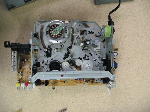
This week for Take Apart Tuesday we dismantled both a VCR and a DVR. The VCR definitely wins for me hands down in terms of fun. More gears and motors and opportunities to take video… although it was pointed out by Gabriel that I shouldn’t be so hard on the DVR. It does have a fan motor and a motor in the hard drive. Okay, okay, fine.
But look at this! DVRs don’t do this!
I’m going to spend a little more time on power sources again because last week I sort of glazed over some details on how not to kill yourself.
But you can always skip that and go look at the VCR cat feeder they made over at Make or the toaster on Instructibles.
Anatomy of a VCR
There is a nice article on how VCRs work at How Stuff Works which covers the basic anatomy. It should be pretty easy to identify the major players on the photos posted on Flickr. I’ve tried to do some commenting there.
There is alsothe wiki page where I’ve broken down sections that other people should feel free write up.
• the Video Processing
• the Motors
• the Power Supply
• the UI (buttons and how they look to the people vs the circuit)
• the Tape Verification (there are some nifty tricks with diodes & beam breaks going on…)
• the Magnetic Tape Readers (Think Sonic Fabric )
The Power Supply
Compared to last week, this power supply was different in a few ways. For starters it isn’t on a separate board, so it would be harder to harvest (but not impossible – think jewelers saw, a dust mask and goggles). Also, it uses 4 separate diodes in its AC to DC conversion rather than a pre-packaged rectifier.
It is cheaper and more space efficient to have all the electronics on one board. Because the power requirements of a VCR are so much less than the monitor’s it is easier to get away with doing that. A VCR pulls less juice out of the wall so it needs a less robust power management circuit.
Before you get out the sharpie and the saw these are the things you’ll want to do:
1: Uplug (Switch off all switches, unplug the unit, remove batteries)
2: Check Fuse (check continuity across the component)
3: Discharge Capacitor (Create a safe short across the leads)
4: Check the AC -> DC conversion (hello high power)
5: Check the DC -> DC voltage drops (making it usable)
Unplug and Fuse Check
I’m going to assume steps 1 & 2 are pretty clear. If step two isn’t here is a great tutorial on How To Use a Multimeter
Discharging A Capacitor
Step 3 can be a little controversial. I apparently created shock and awe by using a rubber handled screwdriver to rapidly discharging the main cap with a spark because I felt reasonably comfortable doing that with a capacitor the size used on the VCR board. Not really recommended. (Understatement.)
Ideally what you’d want to do is put something between the two ends of the capacitor the represents some kind of load relative to the voltage potential of the capacitor. A small lightbulb (not really an LED), a small motor or even just a big enough resistor.
The more voltage that the capacitor could have potentially stored, the more work you want to require of it to escape… but there is a balance between safety and speed: too much resistance and you’ll be waiting all day, too little and there is sparking. I got the ratio 5 to 50 Ohms / V rating of Cap from repairfaq.org.
Here is a way I could have done it better:

Shown is a 1k resistor (brown-black-red), the smallest recommended for a 200V capacitor.
AC to DC conversion
Honestly, the Wikipedia article on this one is pretty darn good. It is called Rectifier
Brief summary:
AC stands for Alternating Current, DC for Direct Current. AC oscillates. It buzzes in two directions. If your circuit is a DC circuit, you need it all to move in one direction.
Those of you who know about diodes are instantly thinking – oh, lets just put a super sturdy diode in there and then we’ll just get the power going one way – which is true but that would be wasteful (you’d only ever use half of whats available to you) and stuttery (Your circuit would only be receiving power half the time).
However, you can use 4 diodes in a bridge rectifier to get a smoother more efficient conversion called Full Wave Rectification. Here is an image from wikipedia to which I’ve added some additional labels so we can compare it to our actual circuit.
The R is technically a resistor, but it serves as a stand-in for whatever work you need that circuit to do; in our case that’s “insert VCR here.” Sometimes you might see it drawn more like this.
Notice that I’ve added a capacitor across the B wire to the D wire to ground. That cap is the big cap we talked about discharging. It looks like a short, but it only acts like one when there is a flood of power into the circuit. The size of this capacitor is determined by how much power would be considered a “flood” by the electronics downstream: Too small and the circuit after it could end up starved for juice, too large and the circuit will end up inundated before the capacitor has a chance to do its job.
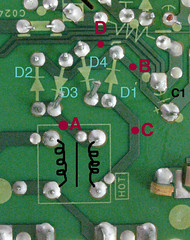
So, when looking at the actual circuit board where do you put the probes to check the DC voltage drop? The following image is of our board, with the same labels as the two circuit diagrams.
So to see the full voltage drop, check between D and B. On this circuit you’ll get around 160 V. Between any two consecutive points (A to B, B to C…) you’ll see around 55 to 60 V.
This is all in comparison to last week where the manufacturers used an integrated circuit with a heat sink attached to do the same thing partially because that board pulls much more current.
 |
 |
DC stepping down
Now, most parts don’t want 160 V – a low power Arduino, for example, needs about only about 3.3V. Many modern devices combine multiple circuits all prefering different amounts of voltage.
That is what that big blue boxy-looking part is – a transformer to step the power down to useable voltages.
The thing is, transformers don’t work with DC voltages. The section of the circuit between the bridge rectifier and the transformer makes the DC voltage pulse at a rate much higher than AC out of the wall does.
I’m not going to dwell on this part expect to say that the usable voltage doesn’t really show up until after the second set of diodes, where on this circuit you get readings of around 12V, around 5V and around 40V. These supply lines probably get split/regulated/filtered, etc further into the circuit, but for stealing power this is where you could stop.
Stop!


grat writeup. sry i missed the first public meeting.
Great writeup Carlyn! This isn’t just Take Apart Tuesday. It’s Figure It Out Tuesday!