
Famikey or: How I Learned to Stop Worrying and Love the Membrane
CRASH Space welcomes guest writer Lucas Leadbetter as he shares his recent love for keyboards with the CRASH community
For anyone that knows me, you know that I absolutely love computer keyboards, specifically mechanical ones.
I’ve always been enthralled by them, the tactility and usefulness makes me enjoy using them and collecting them. But more than that, I love finding the most unique and absurd keyboards, ones that push the limits of what is useful.
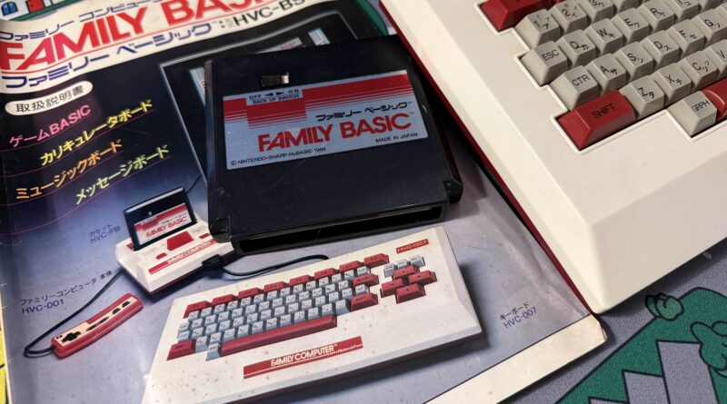
And that leads me to my most recent project: a USB-compatible Family BASIC keyboard, originally for the Famicom.
But… why?
Simply put: I just thought it’d be neat. I stumbled upon the keyboard in a used game shop in Brooklyn, and as soon as I saw it I realized I wanted to make it compatible with a PC. The keyboard itself is so unique, and the fact the badge says “Nintendo” on it and is legitimately a Nintendo product is fascinating as a computer peripheral!
But the bigger problem was that I had zero practical experience with writing microcontroller code, especially as it pertains to more complex (ish) things like keyboard matrixes and scanning for updates.
What is Family Basic?
Taking a step back, Family BASIC was a product designed for the Family Computer (widely known as the Famicom) to enable users to build games in BASIC (Beginner’s All-Purpose Symbolic Instruction Code) for the console.
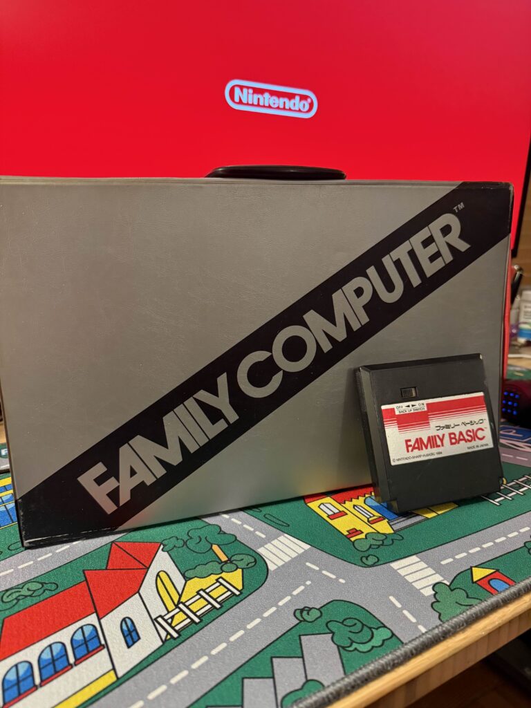
The product itself came with the cartridge for the Famicom as well as the noted keyboard. See Wikipedia for a bit more info.
What is to note is that the layout of the keyboard is specifically designed with BASIC in mind, with specific keys noted for that purpose, which means that it can be kludgy to use with modern PCs.
Preparation
Before getting started, I did a lot of research. I bought a keyboard, but the next step was to find out what exactly would be needed to make this work. The keyboard is from a release in 1984- so much of what I’m working with is relatively old tech (40+ years old at this point), so being cautious was paramount as to not ruin vintage tech.
During that preparation, I found a bunch of information across the internet, but nothing centralized.
NESdev Wiki
One of the biggest sources of information (which is also used by the next source) was the NESdev Wiki. Specifically this resource.
This included a lot of information about the layout and technical implementation, and was actually where I initially started to ponder the implementation of the microcontroller code. Importantly, it also includes the column and row information which is helpful beyond words, as well as links at the very bottom to the keyboard schematics, which is also infinitely helpful (and will come up soon!).
CircuitRewind’s Implementation
CircuitRewind actually beat me to the punch here. He had a video on this exact topic.
And most importantly, he also open sourced his code for the matrix polling logic, designed for the RP2040 microcontroller. This was invaluable – it gave me an immediate start point, including pinouts that could be used to solder up the microcontroller to a cut-up DA-15 expansion connector. I cannot thank him enough for this, and putting this out in the world, and I highly, highly recommend checking his channel out. For a smaller channel, this niche project had a concrete answer that it was both possible and was already done. So while this project wasn’t going to be a 1 of 1, it could at least be a 1 of 2.
Internal Photos
The one thing that eluded me for a long time was the lack of any good photos of the internals of the keyboard. CircuitRewind’s video was a great source for many things, and it actually got me into one important design decision I’ll talk about later, but it didn’t show the internals clearly at times as it was likely cut for purposes of making good content- but for my purposes, it was lacking.
After much digging, I came across two different places with good to great photos.
The first being this blog from 2019.
And the second being this post from Emu-Land’s forum from 2018.
The latter of which is what actually got me what I needed: concrete answers to what is going on in the inside, how the keyboard works from the POV of a mechanical keyboard enthusiast, and high-resolution photos of the connectors as well.
These photos confirmed what I had figured- it was an early 80s membrane keyboard, so it’d feel awful to type on, but the actual mechanics were relatively simple and there was a real PCB in the shell.
Planning
Now that I had information, I could start to formulate a plan of attack.
As I had mentioned prior, the one thing that the CircuitRewind’s video showed me was that the DA-15 cable was not, in fact, soldered onto the board, but rather a plug into the PCB, meaning it could be possible (in theory) to do a non-destructive mod where it would just be a simple microcontroller, a USB cable, and some sort of adapter, and you could always return it to be the Family BASIC keyboard for the Famicom.
This became my biggest goal, in fact. In all reality, it’s likely that I won’t ever need to revert it back to a Famicom keyboard, but there is an element here that preserving tech history is very important, and destroying even a piece of a relatively obscure product (obscure in the states, that is) is not good. Plus it’s cool, ya know?
Secondly, it helped the whole project to become easier in some ways, as well as being far more repeatable if any of y’all want to do it as well. I’ll include a BoM lower down if you’d like to do so- should be relatively cheap once you know what you need (I did not, and bought a lot of extra stuff).
It took a few weeks for me to get the first of two Family BASIC keyboards in. Why two? Well, I figured I might break the first, so a second would be the pretty one I could use. Spoilers: I didn’t need the second one.
Once I got the board, however, I realized that some of the parts I purchased ahead of time that I waited for weren’t correct. But it also did make things a lot easier to do, since the correct parts were readily available. Notably, the connector was specific and very likely out of production.
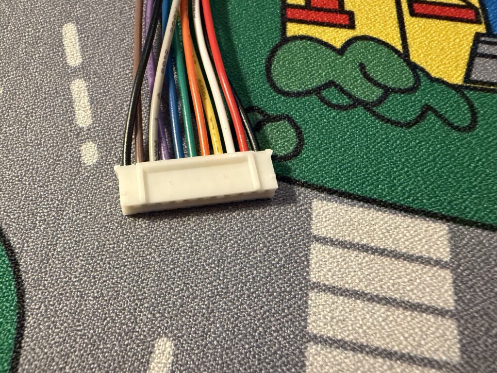
The connector looked like so:
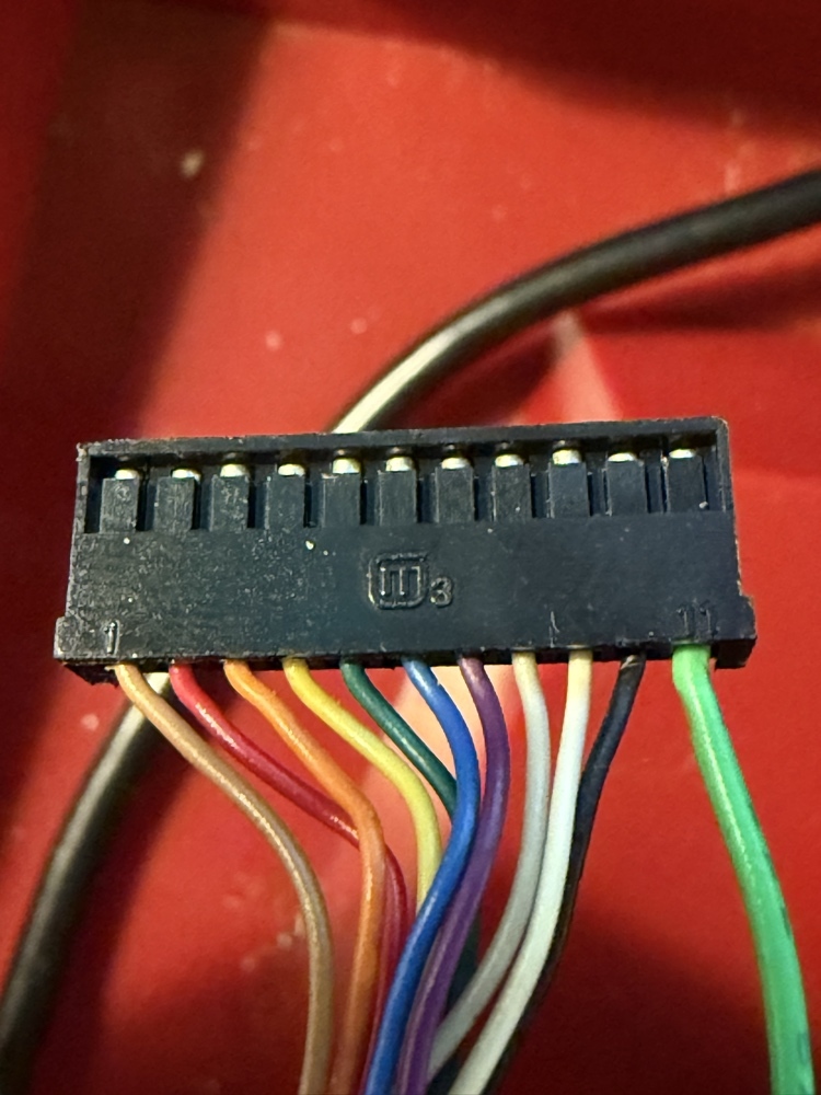
It was a 2.0mm pitch, 11 pin single row connector- not 2.5mm pitch connector as I had assumed.
Original DA-15 Cable Reference for the Family Basic Keyboard
For reference if you have the original DA-15 connector – this shows the original cable’s wire colors and their functions (physical order, from pin 1 to 11 as noted on the connector’s 1 and 11 markings):
| Pin Number | Original Color | DA-15 Pin | Function |
|---|---|---|---|
| 1 | Brown | 01 | Logic Ground |
| 2 | Red | 04 | Data 4 |
| 3 | Orange | 05 | Data 2 |
| 4 | Yellow | 06 | Data 3 |
| 5 | Green | 07 | Data 1 |
| 6 | Blue | 10 | OUT2 (Enable) |
| 7 | Purple | 11 | OUT1 (Col Sel) |
| 8 | Gray | 12 | OUT0 (Reset) |
| 9 | White | 13 | Extra Data (unused for this project) |
| 10 | Black | 15 | Power (VCC) |
| 11 | Light Green | Chassis | Chassis Ground (bypassed DA-15 connector) |
Build Guide
The guide is actually pretty straightforward once you have the right parts, and with everything ready to go, it can take about an hour to mod it, including soldering.
Bill of Materials (BoM)
Here’s the CSV to download if you’d prefer:
| Quantity | Name | Description | Link |
|---|---|---|---|
| 1 | JST PH 11-pin single-row connector w/ attached leads | Used to connect the KB2040 to the DA-15 port; the one linked is a pack of 20, so consider other sources if you can find something cheaper | https://www.amazon.com/dp/B0DMZM59QS |
| 1 | KB2040 | The primary microcontroller; other options may work, but will require source code adjustments | https://www.adafruit.com/product/5302 |
| 1 | 26 AWG wire | Used to connect ground from KB2040 to the chassis | |
| 1 | Silicone USB-C to USB-A cable | This is pretty much up to you on what the other end is, but I find USB-A to be a little more common with PCs to connect a keyboard to. The only important thing is to have it be silicone to be easily routable. | https://www.amazon.com/dp/B0CRZ6KLZM |
| 1 | Kapton tape | Used to wrap the KB2040 (and soldered pads) so it doesn’t short on the metal chassis; consider a wider width if needed. | https://www.amazon.com/dp/B07F8TZZ4N |
| 2 | (Optional) Heat shrink/wire caps | To cover the end of two extra wires from the connector; alternatively can use Kapton tape or similar to prevent the ends from shorting out. | |
| – | Soldering Iron | ||
| – | Solder | ||
| – | Wire Strippers | Removing insulation from extra wire for chassis ground | |
| – | Flush Cutters | Trimming JST PH connector housing |
Assembly
Now that I had (or you have) all the necessary components, let’s actually get to building. In general, it breaks down into a few steps.
Disassembly
Disassembling the Family BASIC keyboard is relatively easy. The bottom of the keyboard has 6 screws- 3 on the top and 3 on the bottom. Due to the age of these keyboards, which are now 40+ years old and entirely made of plastic, being careful is really important. The screws go into plastic posts which can shear due to the screws likely never being unscrewed over the years.
If the posts do shear, use a little epoxy or and just be careful reassembling (and likely plan on never taking it apart again).
Once you’ve unscrewed the base, then carefully pull the bottom off, noting that the DA-15 cable is routed through the bottom case. To get it fully off, you will need to remove the grommet and pull the cable out of the strain relief, unscrew the light green wire from the metal chassis (there’s a spade connector, so it doesn’t need to be unscrewed fully), and then unplug the connector housing from the PCB.
The PCB is only fixed in through some plastic posts- the same “be careful” advice applies here, although I never had issues with fragility.
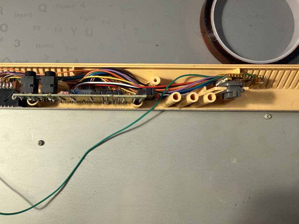
Unplugging the connector might be challenging, so using something thin or a plastic spudger can help here. The PCB would look like:
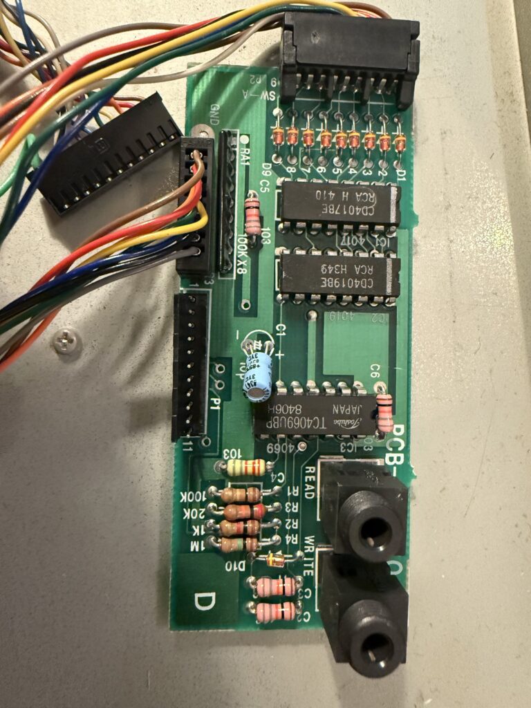
The DA-15 connects into the P1 slot, which is along the side of the board. I found that keeping the other two connectors attached was easier than fully disconnecting.
The grommet is actually reusable, and I’d encourage doing so since it’ll prevent the USB cable from being cut by the plastic, as well as making the install look significantly cleaner.
Trim the JST Connector
The next step is to take the JST PH connector and trim the back plastic flush against the connector housing using flush cutters. Without this the connector presses a little too much for my liking against the socket backplate, so doing this just makes it a little easier. With that said, I’m also not fussed about the risk of disconnection since we’ll use the strain relief posts to help mitigate the amount of pull on the KB2040, and as a result, the connector itself will experience little pull.
Here’s the untrimmed connector:
And a resulting connector:
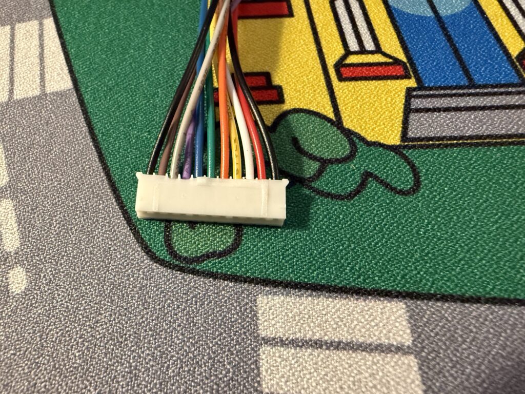
You can test it by plugging the connector in and trimming as needed.
Solder the Wires to the KB2040 and Screw Wire to Chassis
The next step is the more complicated one, but just because it takes some time.
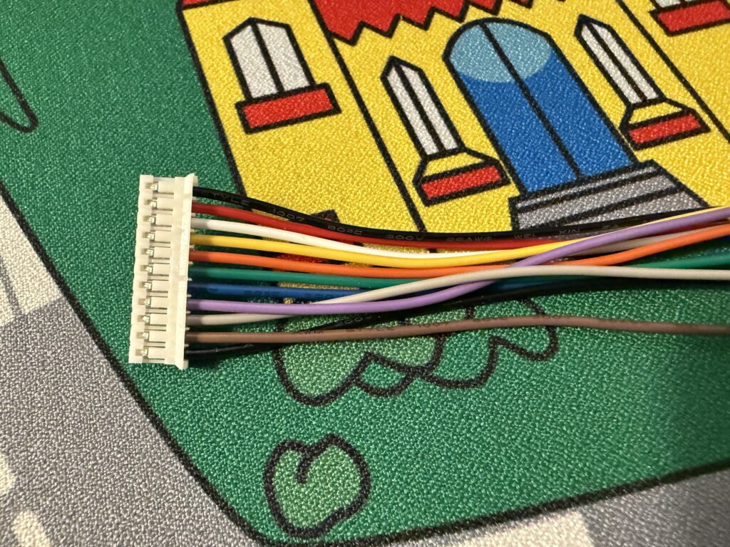
Note: The very first wire (black in this case) is not used. The wire mapping here is mostly to show where to solder the wires and as a mapping to the old connector, so you’ll see there’s an extra. Tape it off, just like the new white cable.
The mapping looks like:
| Original Color | Wire Color | KB2040 Socket | GPIO | Function |
|---|---|---|---|---|
| Lt. Green | Extra 26 AWG wire (solder to GND pad) | GND | GND | Chassis Ground |
| Black | Red | 3.3V | 3V3 | Power (VCC) |
| White | White (tape off) | – | – | Not Connected |
| Gray | Yellow | D2 | GP2 | OUT0 (Reset) |
| Purple | Orange | D3 | GP3 | OUT1 (Col Sel) |
| Blue | Green | D4 | GP4 | OUT2 (Enable) |
| Green | Blue | A0 | GP26 | Data Pin 1 |
| Yellow | Purple | A2 | GP28 | Data Pin 3 |
| Orange | Grey | A1 | GP27 | Data Pin 2 |
| Red | Brown | A3 | GP29 | Data Pin 4 |
| Brown | Black | GND | GND | Ground |
The wire color is based on the JST PH connectors I purchased (and linked above).
The ordering will be top-down, if the connector faces to the left, like so:
Next, screw the extra wire (the 26 AWG wire you soldered to GND) to the chassis. At this point, if you’d like to “production-ize” it, you could attach a spade connector like the original cable, or if lazy like me, just strip a little extra cable and wrap around the screw and screw down.
Once finished, it’d look like something like this (where the green wire is the extra one I soldered to the KB2040):
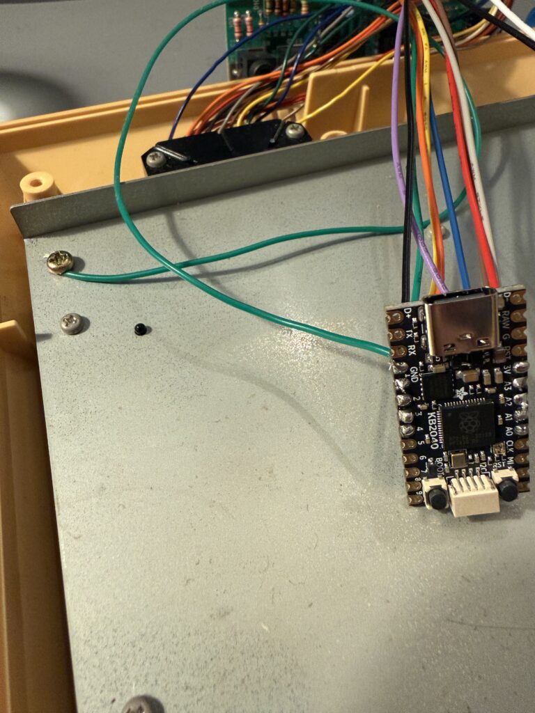
Lastly, plug the KB2040 into the PCB and you’re done with most of the hard work!
Flash the Firmware
Next, I flashed the firmware using the source in https://github.com/lleadbet/famicom-keyboard– the README includes a duplication of some info in this post, but the instructions on how to compile the firmware is included. Once you have the .uf2 file, just start the KB2040 in the bootloader via pressing the BOOT button and plugging the KB2040 into a PC using the USB-C cable and paste the file into the newly mounted drive. The KB2040 will restart at that point.
Once that’s done, you can test the board. Press a few keys and see if it works- if not, check the wire order and that the board is fully plugged in. Other than that, I have no idea ¯\_(ツ)_/¯.
After testing, you should also note that it contains VIA support. The GitHub repo includes information on how to set that up, and I’d encourage you to do so- having modern features on a 40+ year old keyboard is a treat.
Final Assembly
The last steps are to wrap the PCB into Kapton tape, find a spot to put the KB2040, and route the USB cable. Finally, close ‘er up and enjoy your fancy new Family BASIC keyboard on a PC!
The Kapton tape should ideally fully wrap the KB2040, as to prevent any part of the board from shorting on the metal chassis. In an ideal world I’d print a 3D part to slot into the case like the original does, but for a mod this feels sufficient, plus Kapton won’t leave residue.
I found putting the KB2040 into the top shell like so worked fine. Just note to be careful when routing cables, as it can be easy to pinch them when closing up:
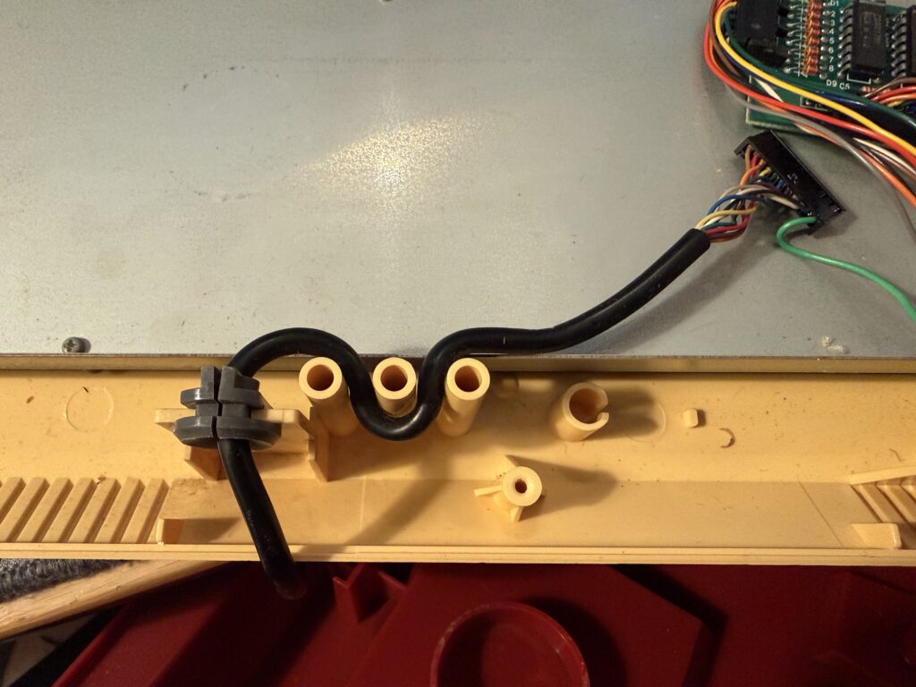
You can use the existing strain relief posts to route the USB cable as well:
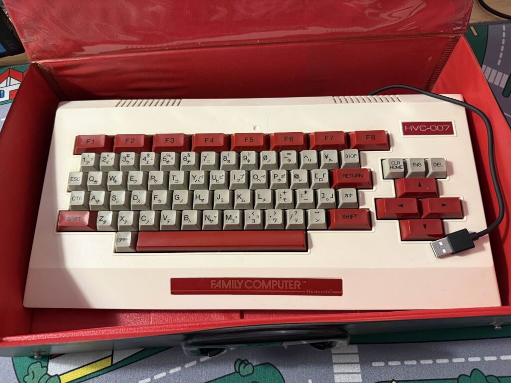
Lastly, here’s how it should look closed up:
Summary
It works! With a combination of prior work I’ve found as well as some newer approaches, I have a working, USB-C compatible Family BASIC keyboard that can be used with VIA to create custom keymaps/layers.
The keyboard isn’t great to use for a daily driver, but as a novelty it’s hard to beat. The membrane sucks to type on… but yet I find it a uniquely enjoyable experience, one that I don’t think I’ve ever had before and still is something I’d love to share with others.
GitHub / Source Code
All source is available on https://github.com/lleadbet/famicom-keyboard, and includes information on how to use. This post mostly serves as the build guide and context behind the build.