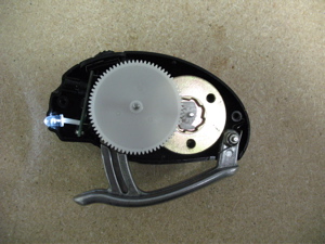
Take Apart Tuesday No 3. : Crank Flashlight

Okay, it seems I’m obsessed with power.
We took apart quite a few things Tuesday night: a massive HD projector from 1996, a little bit of a laptop, an antenna, and various miscellaneous items including a hand crank LED flashlight that Tom brought in.
That little flashlight was fun. Below is a video showing Sean having way too much fun twirling it around.
Conveniently this little device also represents yet another example of AC to DC power generation… the saga continues.
Overview
Not a lot of parts to this one so this time my overview is simply a link to the photo gallery on flickr:
http://www.flickr.com/photos/carlynorama/sets/72157623252086618
I’m afraid we don’t have a plug-in for this yet.
Electromagnetism
Moving electricity creates magnets. Moving magnets create electricity. This is what the right hand rule is all about. This is what creates electromagnets. This especially gets us motors.
Two very different reviews of this are the kid’s version or the semester at MIT version.
My vast simplification is this: Remember how if you have two magnets lining them up one way they attract, the other way they repulse? Motors use this property of magnets to create motion from electricity by having one permanent magnet (like a fridge magnet that is always a magnet) which gets shoved away from the electromagnet created when you turn on the switch and let current flow from the power source.
The crank flashlight flips the motor dynamic entirely around. When the handle of the flashllight gets pumped, it cranks a gear that spins a magnet. That moving magnet then induces an electric current in the wire. Since it would be impractical for a flashlight to have a giant magnet bigger than the size of a building continuously moving in one direction next to the wire, the whole unit spins in a circle. This spinning creates an alternating current that, with a little magic, then puts the charge into a capacitor.
Insert Magic Here
So, you can probably guess what that magic is… full wave rectification using diodes! I knew you had it. In order to get more bang for the buck the inductor they’ve chosen seems to be 3 phase – 3 pole which means we see 3 leads from it to the circuit rather than the 2 from that would come from a basic DC motor.
Looking at the parts and testing some continuity between them, this is my guess to how this circuit is working.
A very good resource I found on battery charging circuits is a project write up for a bike-powered generator.
Is it a battery or a capacitor?
Another great thing about this circuit is it brings up our safety lecture again. Capacitors hold charge and will slowly release it over time. That ability to store power can hurt you or help you. In this circuit it means a person can give their hand a rest!
It is important to note that the capacitor is not a battery. A battery uses a chemical reaction to create free electrons that will move from one end of the battery (the one labeled – ) to the other (the one labeled + ) when given a path through a circuit. A capacitor will store electrons that have been given to it and release them slowly over time.
We created moving electrons with the moving magnet and are storing them in the capacitor. The capacitor then safely discharges over time lighting the LED even after we stop cranking.
And this is where I stop cranking. Hope you enjoy!

